venturi flow meter formula
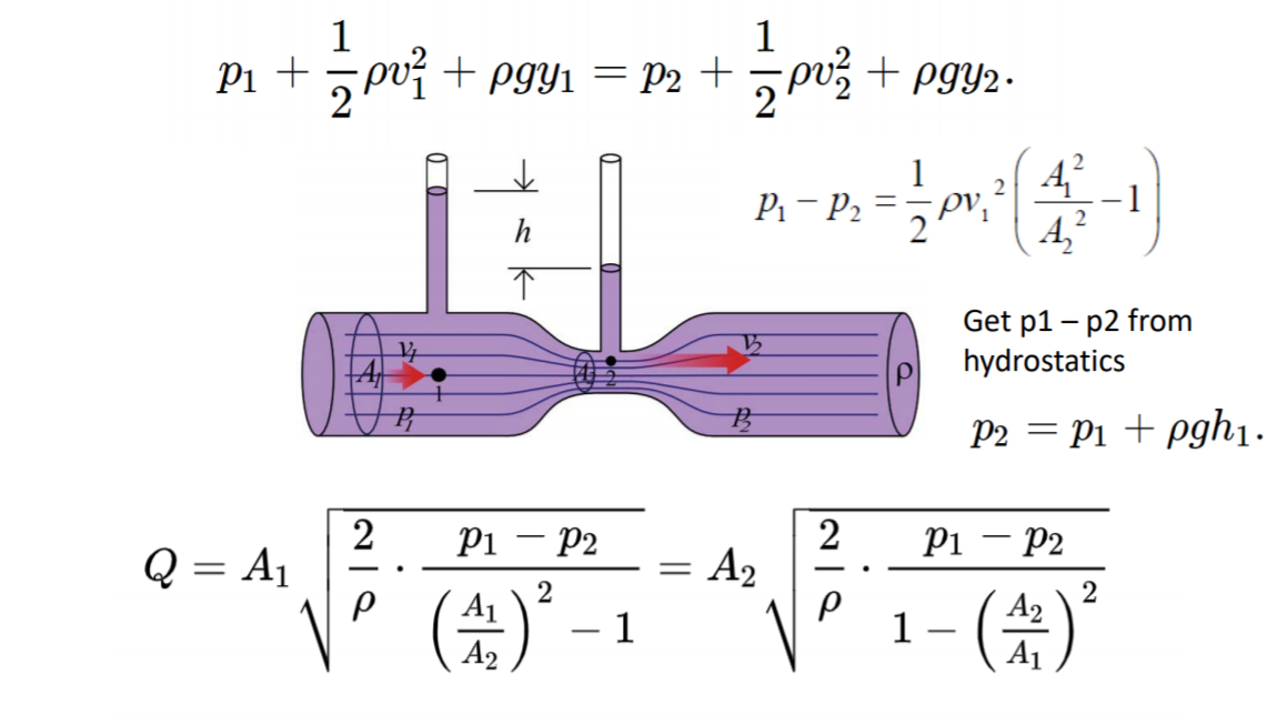
A1 is cross sectional area of first part of the tube Pi R2 0000415 M2 A2 Pi R2 00000283 M2 P Density of air 1225 P1-P2 DeltaP 2222 Pa. P1 12 ρ v12 γ h1 p2 12 ρ v22 γ h2 1b where.
Venturi Meter Design Equations Formulas Calculator Flow Rate
Where C v is the Venturi coefficient A 1 and A 2 are the areas of the pipe cross-section ΔP is the difference between the pressure in A 1 and A 2 and ρair us the density of air.

. Solving for pressure differential. A Venturi can be used to measure the volumetric flow rate using Bernoullis principle. W mass flow rate lbms V velocity of stream fps A flow area ft 2 π r 2 area of circle g c gravitational constant 32174 lbmftlbfs 2 ρ density of fluid lbmft 3 p 1 absolute pressure lbf ft 2 p 2 gauge pressure lbf ft 2 β ratio of diameters D 2 D 1 for venturi and sharp-edge orifice and d D for flow nozzle D pipe diameter.
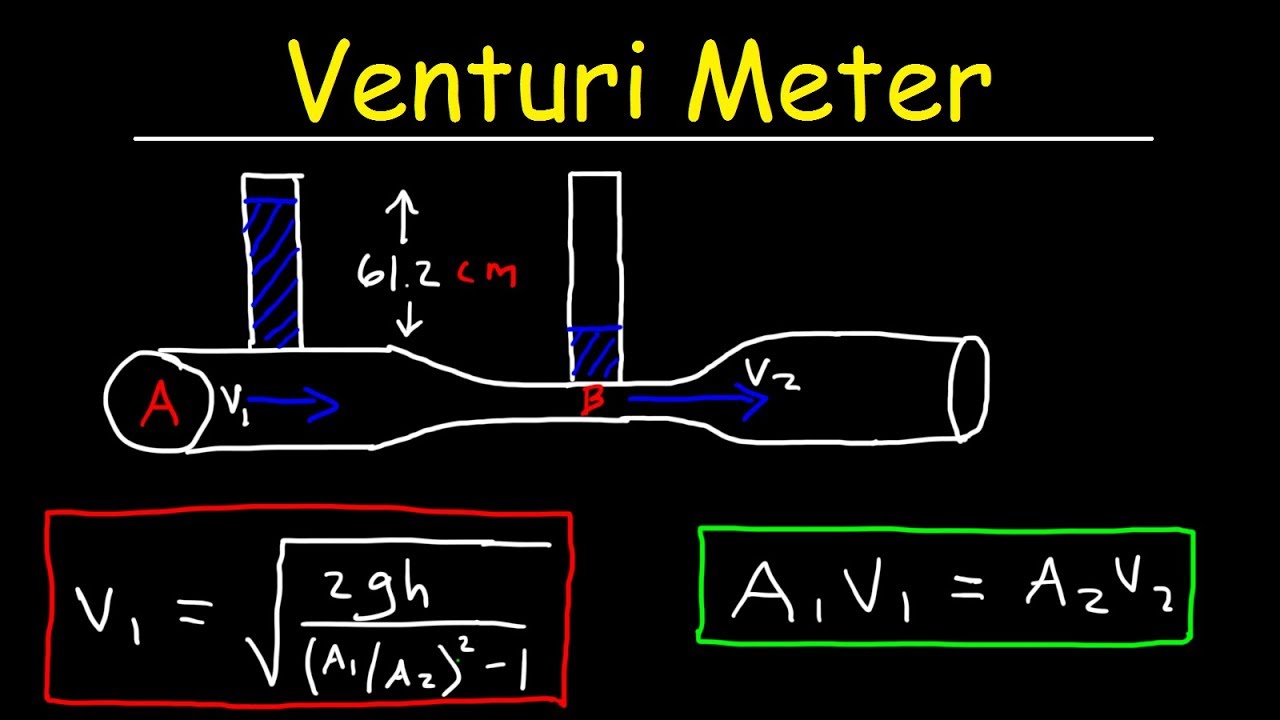
γ specific weight of fluid kgm3 slugsft3 h elevation m ft Assuming uniform velocity profiles in the upstream and downstream flow - the Continuity Equation can be expressed as. Select a venturi using the following sizing considerations. This flow rate is related to both the cross-sectional area of the pipe and the speed of the fluid thus with the continuity equation.
What is the included angle of a venturi meters divergent cone. They have been in common use for many years especially in the water supply industry. In this conditions we can use both the continuity equation and Bernoullis equation to solve the problem.
So the venturi meter discharge coefficient is given by. Based on the conditions of the experiment C v equals 08159. If we want to find actual discharge then we will multiply the coefficient of discharge into the theoretical discharge.
A fluid passing through smoothly varying constrictions experience changes in velocity and pressure. Units in Venturi Flow Meter calculator. Capacity chart 60F and 14696 psia using the formula.
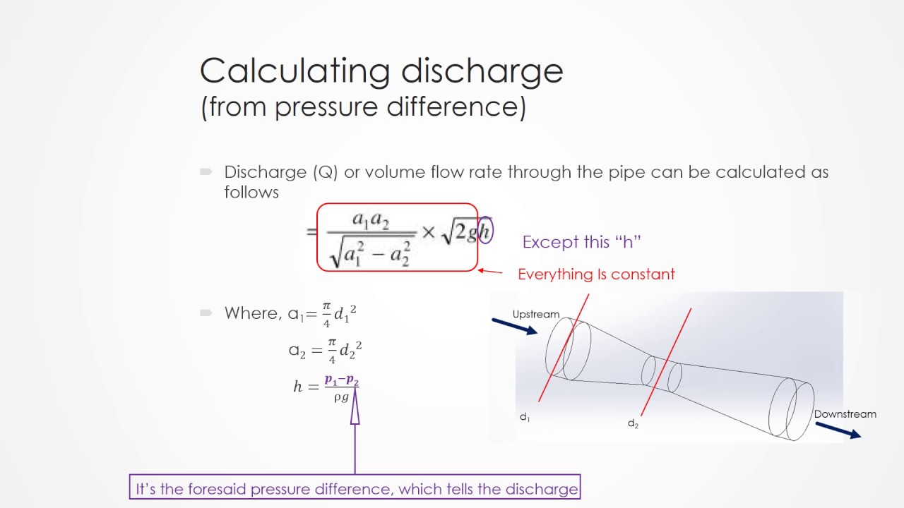
The venturimeter basically works on the principle of Bernoullis equation. The volumetric flow rate is defined as the volume of fluid flowing through the pipe per unit time. And the pipe Reynolds number Re.
Q v1 A1 v2 A2 2 where. The pipe diameter D1. C d Q act Q.
To find the Coefficient of discharge then we have to divide actual discharge by the theoretical discharge. Reynolds number calculated at the Venturi tube throat q 1 - volumetric flow rate Fluid flow rate in terms of units of volume per unit of time on the inlet conditions q - standard flow Flow rate at standard conditions. The venturi meter device measures the flow rate or velocity of a fluid through a pipe.
The equation is based on the Bernoulli equation conservation of energy and the continuity equation. 2014 LMNO Engineering Research and Software Ltd. The venturi meter device measures the flow rate or velocity of a fluid through a pipe.
In the venturi meter the fluid flow rate is reduced due to the reduction of the cross-sectional area. Qactual Cd X A2 X v2gv1-A2A12 X vh1-h2_____5 In a pipe there are two types of flow brought about by varying velocities. Lets assume a steady flow through the pipe.
Pipe Area A pipe m 2. Q2 250000 264438 scfh 2. The diameter ratio β.
Gallon kgkilogram kmkilometer lbpound mmeter minminute NNewton PaPascal psilbinch 2 ssecond. As the fluid enters the converging section its velocity begins to increase reaching a maximum value. The coefficient of discharge for Venturimeter Cd is defined as the ratio of the actual flow rate through the venturi meter tube to the theoretical flow rate.
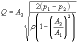
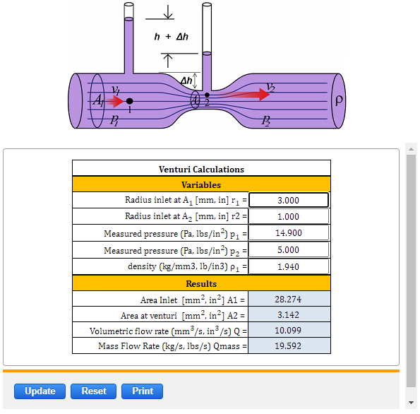
Q volumetric flow rate m 3 s in 3 s Q mass Mass flowrate kgs lbss A 1 area Π r 2 mm 2 in 2 A 2 area Π r 2 mm 2 in 2 r 1 radius inlet at A 1 mm in r 2 radius inlet at A 2 mm in p 1 Measured pressure Pa lbin 2 p 2 Measured pressure Pa lbin 2 ρ density kgm 3 lbin 3. Solving For Flow Rate. To calculate the flowrate of a fluid passing through a venturi enter the parameters below.
For an orifice meter with one of the three ISO standard pressure tap configurations corner taps flange taps or D-D2 taps ISO 5167 provides an equation for the orifice coefficient C in. These flows are called laminar and turbulent flow. These changes can be used to measure the flowrate of the fluid.
Any point of flowing fluid in the venturi meter there will be pressure energy potential energy and kinetic energy. Turbulent flow Re 4000 Laminar flow Re 2000 Using Reynolds equation. I am using Bernoulli Equation of the Venturi meter as above From my MPX5010 DP Sensor I am getting a pressure differential of 2222 pa.
Cmcentimeter ftfoot ggram galUS. The venturi should not be sized at this point to avoid transmitter saturation. The length of the convergent cone of a venturi meter is found with formula D-d where D Diameter of inlet section and d diameter of the throat.
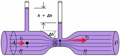
Suppose the quantity of liquid v1 enter to the pipe as per continuity equation volume flow rate at the inlet Q1 is equal to discharge at the outlet Q2 so if v1 amount of water enters to the inlet of the venturi meter the same amount of water should be discharged at the outlet that means at unit second v1t1 v2t2. Differential pressure dp column is maximum fl ow. The principle behind the operation of the Venturi meter or venturi tube is the Bernoulli effect as well as the Continuity equation.
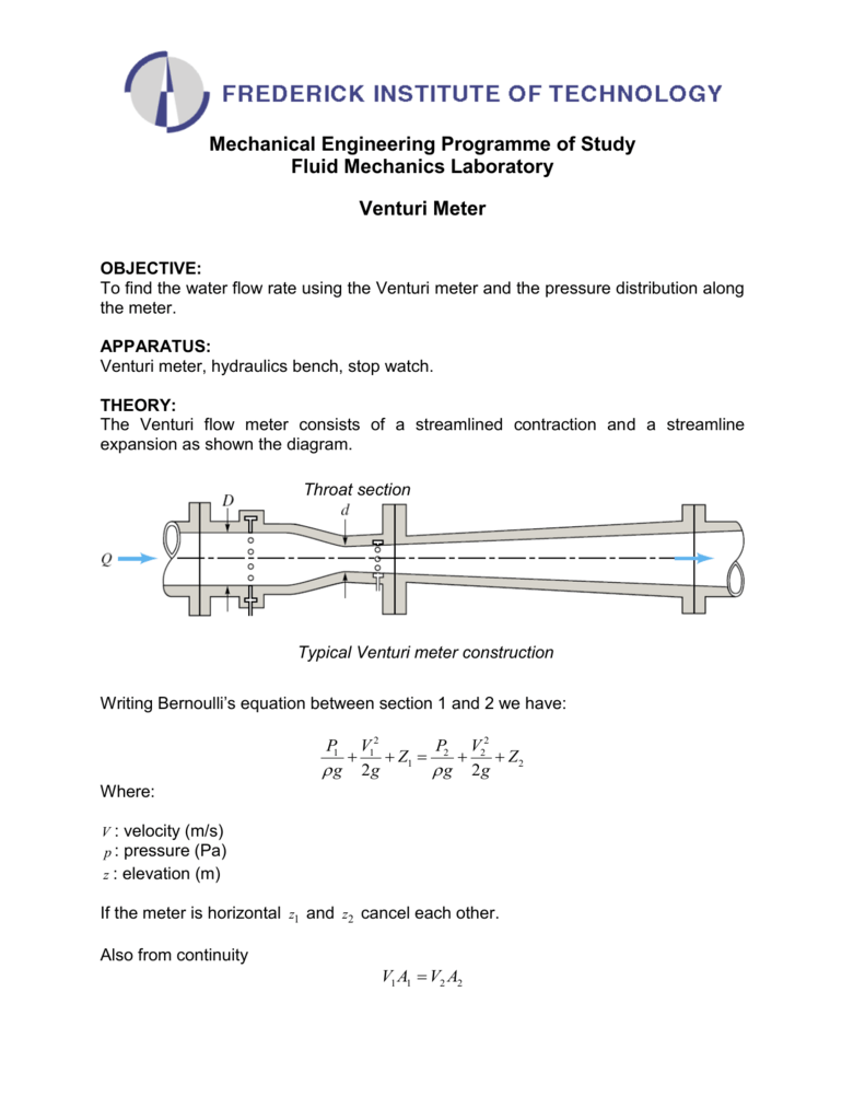
It consists of a converging portion throat and diverging portion. Venturi meters are flow measurement instruments which use a converging section of pipe to give an increase in the flow velocity and a corresponding pressure drop from which the flowrate can be deduced. The meter consists of a converging inlet section a short straight throat section and a diverging section.
They are used for measuring the flow rate of compressible and incompressible flow in pipelines. The venturi flow meter is installed as a section of pipe or tubing and is used to measure the flow of fluids either gaseous or liquid. Venturi meter Length of the venturi meter 16mm Entrance diameter D 1 16mm Throat diameter D 2 7mm Length 8mm Cross-sectional area of the throat S 2 π D 2 24 β D 2D 1 Collector Tank Readings Manometer Reading Coefficient of discharge é Initial water level cm Final water level cm Time taken sec Flow rate Q m3sec h 1.
The discharge of flow in the venturi meter will be calculated as. Used only if the selected fluid is gas. Terms of the pressure tap locations L1 and L2.
Since Q v 1 A 1 v 2 A 2 p 1 p 2 ρ 2 v 2 2 v 1 2 displaystyle beginalignedQv_1A_1v_2A_23ptp_1-p_2frac rho 2leftv_22-v_12rightendaligned. According to the formula the flow rate can be calculated according to the following formula. ṁ - mass flow rate Fluid flow rate in terms of units of mass per unit of time V 1 - upstream velocity.
The equation is based on the Bernoulli equation conservation of energy and the continuity equation.

Chapter 11 Example 11 The Venturi Meter Youtube
Venturi Meter Problems Bernolli S Principle Equation Of Continuity Fluid Dynamics Youtube

Venturi Meter Definition Parts Working Derivation Applications Pdf

Flowrate Calculation For A Venturi
No Title
Solved A Formula Is Given For The Volumetric Flow Rate Chegg Com
Venturi Flow Equation And Calculator
Venturi Flowmeter Flowmaxx Engineering
Venturi Meter Finding Pressure Difference Physics Forums
Venturi Flow Equation And Calculator

The Venturi Tube Collection Of Solved Problems
Flowrate Calculation For A Venturi
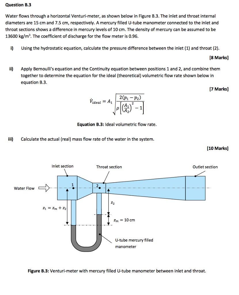
Solved Water Flows Through A Horizontal Venturi Meter As Chegg Com
Venturi Meter

Venturi Meter Engineeringclicks

Bernoulli S Equation Venturi Meter

Theoretical Fluid Mechanics Venturi Meter Mike Soltys Ph D
Venturimeter Pressure Gauges Tells The Rate Of Flow Youtube
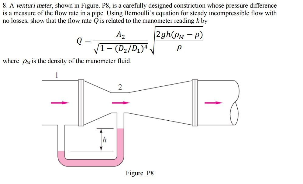
Solved A Venturi Meter Shown In Figure P8 Is A Carefully Chegg Com